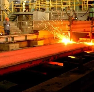
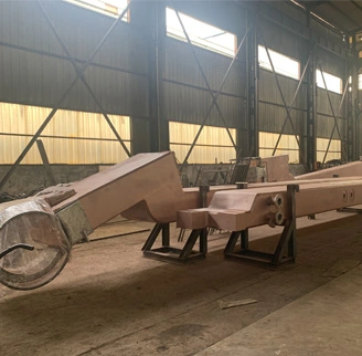
FTP Fume Treatment Plant

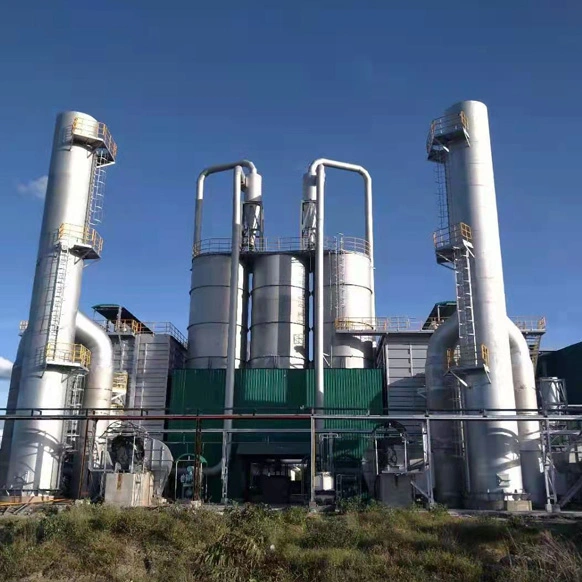
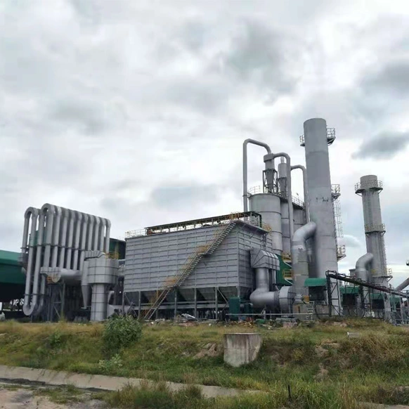
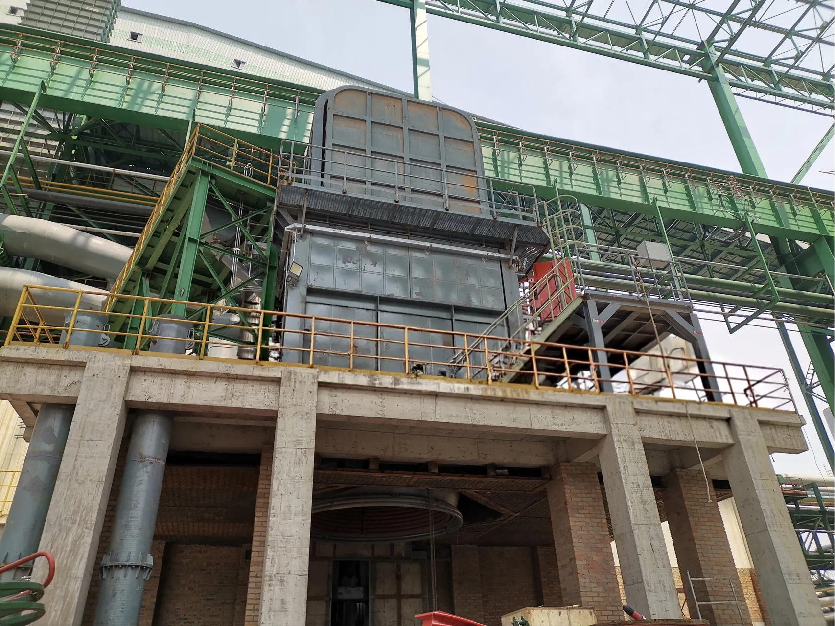
In the fume treatment plant aluminium smelter, the electric furnace flue gas is collected through a gas collection hood and enters the main pipeline. Sparks in the exhaust gas are extinguished through a flame arrester, and then the exhaust gas enters the bag dust removal system. From the inlet of the bag dust collector, dust gas enters the filter area of the warehouse, and the remaining dust enters the filter area evenly with the airflow. The filtered clean gas enters the box through the filter bag. Lift valve. The exhaust pipe is discharged and then discharged to the dust standard through an induced draft fan.


Basic principle - "Dust removal equipment serves the production of the furnace body". Dust removal equipment should not affect the normal production process and operation of the fume treatment plant aluminium smelter, and should not hinder the maintenance and repair of the furnace equipment.


The primary principle is "reliable operation". The system operates reliably and stably for a long time, eliminating common problems such as burning cloth bags, dust accumulation in air ducts, and air volume attenuation.


Adopting advanced technology - designing for the specific conditions of the fume treatment plant aluminium smelter in this project, adopting advanced and mature technology, and not simply applying the model of other similar furnaces.


Excellent performance to price ratio - optimized design, saving investment in one go, low energy consumption during long-term operation, and good environmental protection effect.


FEATURES

Fume Treatment Plant Aluminium Smelter Features

CHNZBTECH fume treatment plant aluminium smelter with small investment, high flexibility, limited dust emission features. Diverse application for traditional top charging EAF, continuous horizontal charging EAF, to ladle furnace, Vacuum Degasser, Submerged arc furnace dust collection. 

Types

Ranges of Products Among Fume Treatment Plant Aluminium Smelter

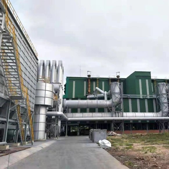
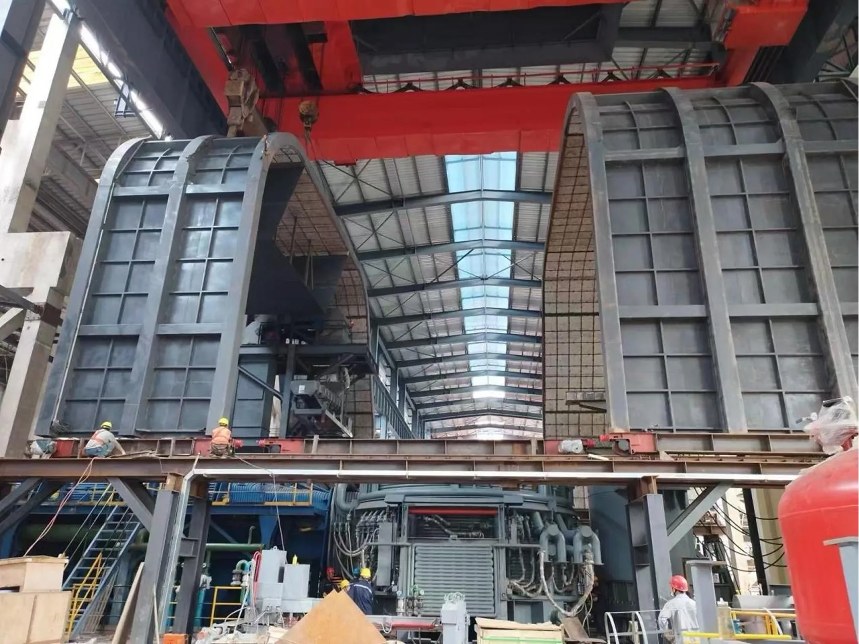
A complete electric furnace dust removal system in a foundry and steel mill includes four parts: dust hood, ventilation duct, dust collector, and fan.

Ventilation duct is a channel for transporting dusty airflow, which connects parts such as the vacuum hood, dust collector shoulder machine, etc. into one. Whether the pipeline design is reasonable or not will affect the effectiveness of the entire dust removal system. Therefore, it is necessary to comprehensively consider various issues in the design of Luodao in order to obtain a more reasonable and effective solution.


WORKING

Working Principle of EAF Dust Removal System

  • Pre treatment: Use a wet or dry dust collector to remove smoke and harmful gases.

  • Filtration: Filter particulate matter, harmful gases, and suspended solids to purify air.

  • Purification: Remove harmful gases, toxins, odors, etc.


COMPOSITION

Composition of Electric Furnace Dust Removal System

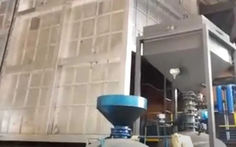
The electric furnace bag dust collector consists of a shell, a filter bag, an ash hopper, an ash discharge device, a bracket, and a pulse cleaning system.

The electric arc furnace dust collector is composed of a box assembly, a filter bag assembly, a guide device, a pulse blowing system, an ash discharge system, a control system, an offline protection system, etc.

The larger the volume of the electric furnace dust collector, the better. This should be based on the on-site operation situation to handle the airflow of the fan and determine the size of the fan model. If the fan is too large, the service life of the shell and accessories of dust collectors of types of steel making furnaces will be greatly damaged. If the fan model is too small, this furnace auxiliary equipment cannot work properly, and the wind speed inside the pipeline cannot meet the requirements. The pipe may cause blockage. Therefore, for a fume treatment plant aluminium smelter, selecting the fan of the electric furnace dust collector reasonably can effectively ensure the normal and stable operation of the dust collector and ensure dust removal efficiency.

It is important for fume treatment plant aluminium smelters to maintain sufficient draft on the furnace for the following reasons:

1. To provide adequate pollution control.

2. Excessive shop emissions make it difficult for the crane operator to charge the furnace.

3. Excessive emissions around the electrode ports can result in damage of hoses, cables, the electrode holder, the furnace delta, roof refractory, accelerated electrode wear, damage to the electrode spray cooler etc.

4. Emissions at the roof ring can result in warping of the roof ring structure.

5. Excessive emissions of carbon monoxide to the secondary canopy system may result in explosions in the ductwork downstream.

6. Excessive dust build-up may cause arcing between electrode phases. Most DES systems consist of water-cooled duct, spray cooling, dry duct and mayor may not have a dedicated DES booster fan.

VIDEO

FUME TREATMENT PLANT ALUMINIUM SMELTER VIDEO

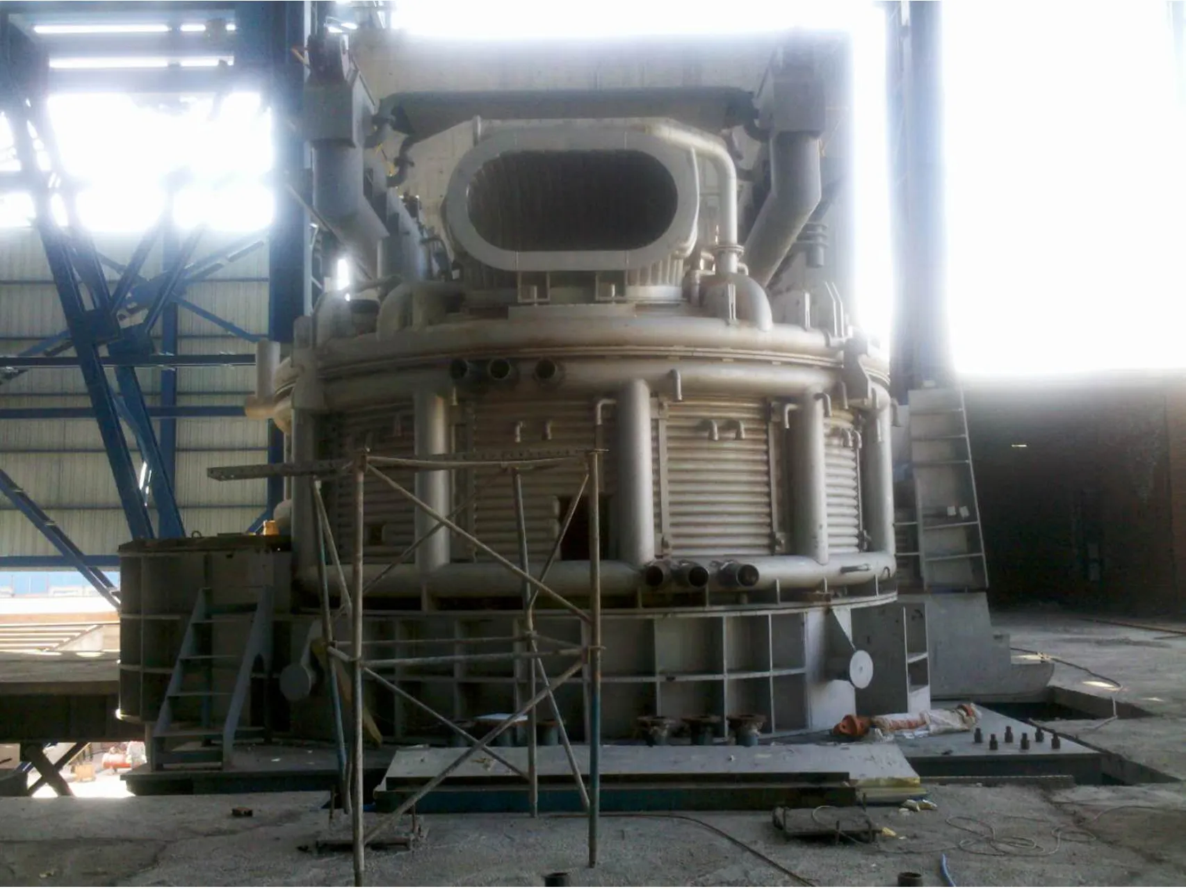
The structure of the fume treatment plant aluminium smelter of a large EAF, LF, dust collector: The dust exhaust hood of the EAF and Induction furnace dust collector can be divided into top suction hood, bottom suction hood, side suction hood, and roof gas collection hood according to its setting position.

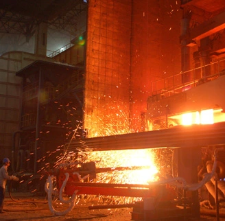
Due to the fact that the smoke and dust generated in the melting and charging process account for the vast majority of the total smoke and dust, we focus on collecting smoke and dust from these two areas.


FUME TREATMENT PLANT ALUMINIUM SMELTER VIDEO
Technical Parameters

ItemTypical Value / RangeRemarks
System TypeCentralized Baghouse (Pulse Jet / Reverse Air)Dry type is standard for metallurgy
Connected SourceEAF, LF, AOD, SAFMulti-source suction is common
Total Treatment Airflow300,000 ~ 1,000,000+ Nm³/hDepends on furnace capacity & hood type
Inlet Gas Temperature120 °C ~ 180 °C (after cooling)Raw fume can be >1000°C; requires cooling (Air/Water)
Filter TypePulse Jet Bag Filter / Cartridge FilterBaghouse is industry standard
Filter Media (Bag)Fiberglass, Nomex (Aramid), PTFE Coated, P84Selected based on temp & chemical resistance
Filtration Velocity (Air-to-Cloth)0.8 ~ 1.2 m/minLower ratio for finer dust/higher efficiency
Total Filter Area5,000 ~ 15,000+ m²Scales with airflow and filtration velocity
Dust Collection Efficiency≥ 99.5% ~ 99.9%
Outlet Emission (Stack)< 10 ~ 30 mg/Nm³Modern systems target < 10 mg/Nm³ or even < 5 mg/Nm³
System Resistance (Pressure Drop)1,200 ~ 2,000 PaAcross the baghouse filter
Induced Draft (ID) Fan Flow300,000 ~ 1,000,000+ Nm³/hMatches system airflow
ID Fan Static Pressure3,000 ~ 6,000 PaDepends on ductwork length and system resistance
ID Fan Power500 ~ 2,500+ kWOften equipped with VFD (Variable Frequency Drive)
Compressed Air (for Pulse)0.4 ~ 0.6 MPaRequired for pulse jet bag cleaning
Dust Handling SystemScrew Conveyor + Rotary Valve / Pneumatic ConveyingFor transferring collected dust to silos
Stack Height20 ~ 50+ metersDesigned per environmental regulations
Control SystemPLC / DCS with Auto Damper & Cleaning ControlIntegrates with furnace operation


CHNZBTECH INDUSTRIAL STEEL MAKING FURNACES
100
Countries
30000
Clients
500+
PROJECTS
2000+
EXPORT
CHNZBTECH